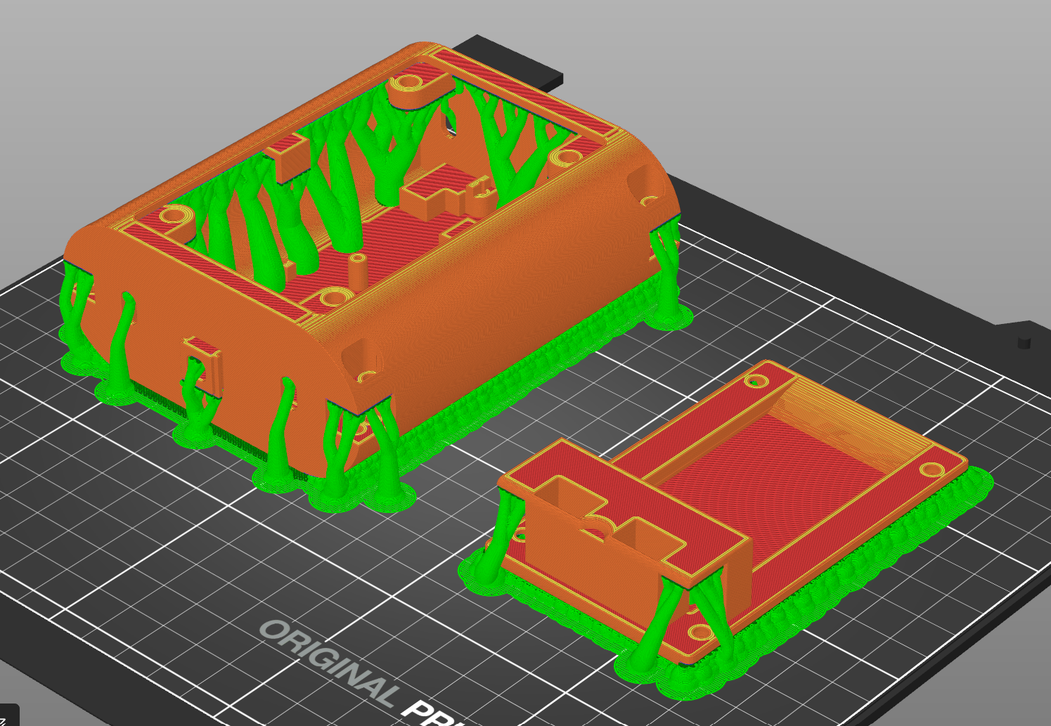
Main Body and Lid
Lots of measuring and mentally pushing components around - a bit like Tetris.
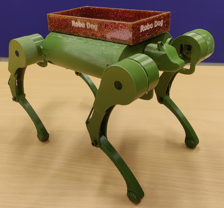
Learn moreThis robotic dog can carry your tools and keep you company wherever or whenever real dogs are not the best solution.
Static Model
When we were looking for something cool to build as our final project for the production engineering course, Jan-Erik and I wanted to create something genuinely useful — so building a quadruped robot that could carry items and follow you felt like the natural choice. We settled on a template we found on hackster.io. In the following I will describe the changes that were made to the original design to accommodate for the additional components needed for the follow-feature, improve traction of the feet and implement the capability to carry tools.
Disclaimer: Due to the relatively high prices of servo motors the finished robot will be a (mostly) functional scale model of what we imagined.
We planned to implement the follow-feature via a radio-transmitter, held by the person to be followed, and receiver built into the Robo Dog. For carrying tools, a tray was to be made by laser cutting. And last but not least, the Robo Dog got cast silicone feet for enhanced traction.
Some parts could be kept the same as in the template, others had to be modified to fit the components we wanted to use or for overall functionality and some were designed from scratch.
(for the design and build process of the electrical components please see Jan-Erik's page)
Before anything could be modified or changed all .stl files had to be converted to .step to make alteration possible.
Take a look at how each of the - modified and new - parts came to be.
Lots of measuring and mentally pushing components around - a bit like Tetris.
Learn more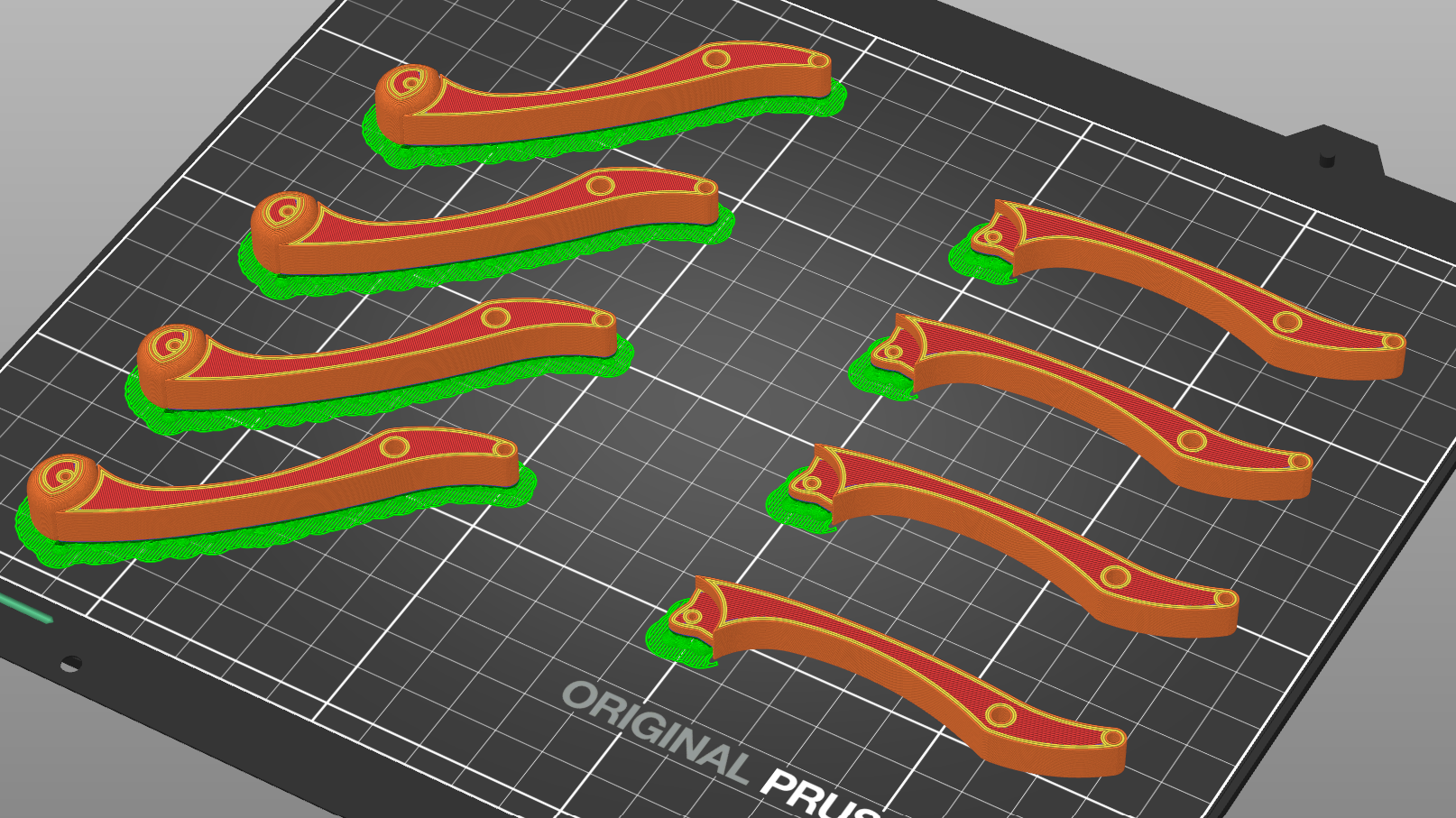
A steep learning curve and some fascinating discoveries on my part.
Learn more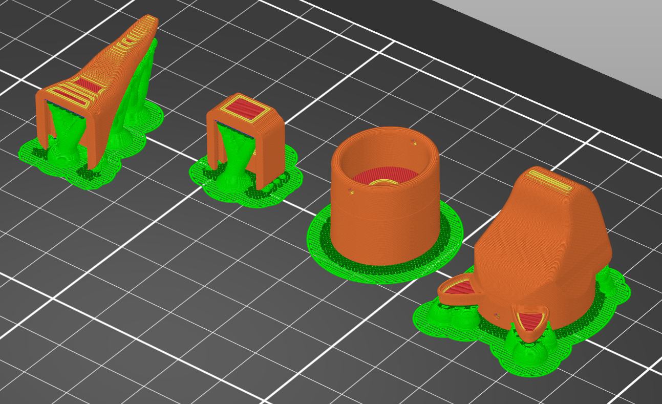
Some a bit more creative work for a change.
Learn more
Taking a break from 3D-printing.
Learn moreAfter completing the designs described above, everything that was left to do, was to assemble RoboDog. This meant connecting modified, new and unchanged parts and most importantly: fitting the electronics into the body!
While some components, like the tray, the USB-Port, the battery in the lid and the head and tail fit according to plan, some did not.
The electronic componnets each fit in their own layer, but a combined assembly was not possible due to lack of space. Possible (future) solutions include building a larger model and custom printed boards (for the current size model). Custom boards would drastically cut down the size and number of components, as well as the amount of wires, needed.
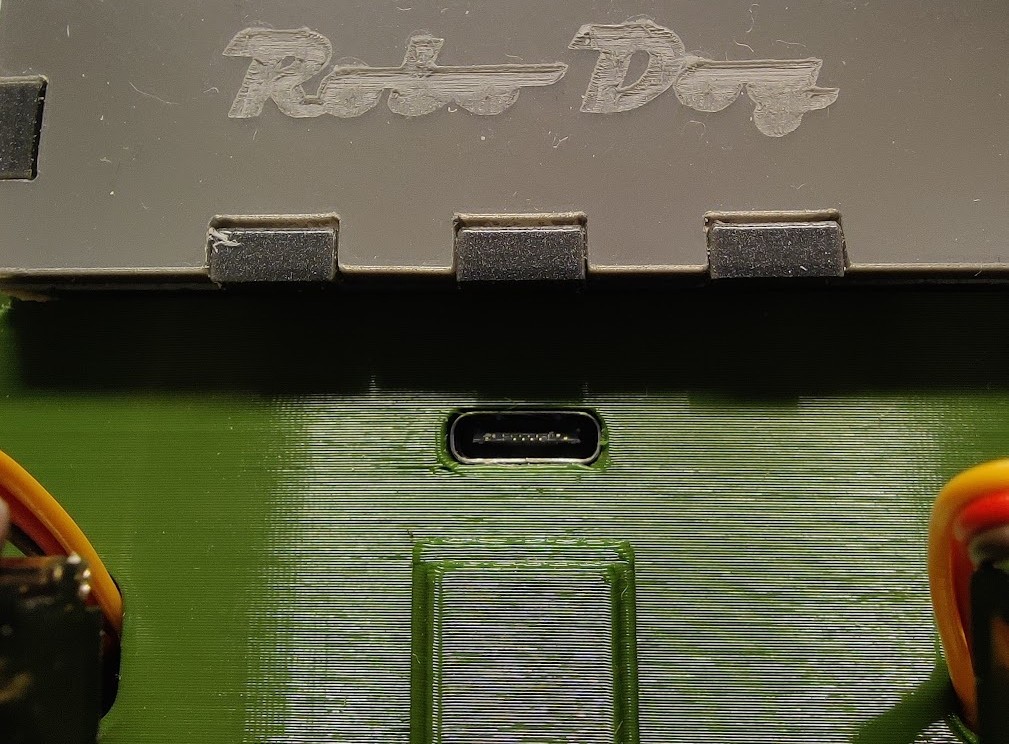
Fit of the USB-Port
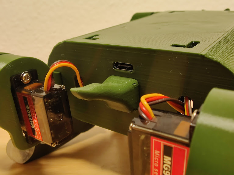
Tail mounted
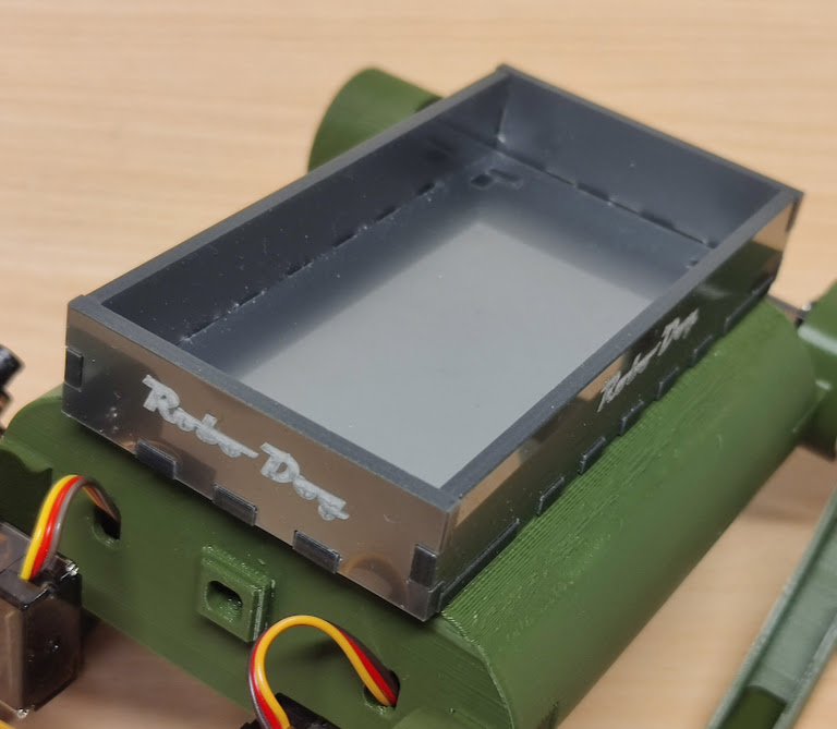
Tray installed
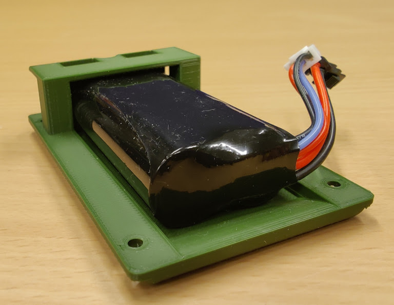
Battery in the Lid
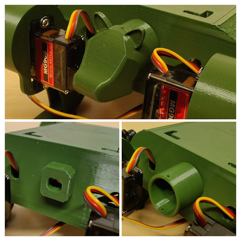
Assembly of Head and Neck
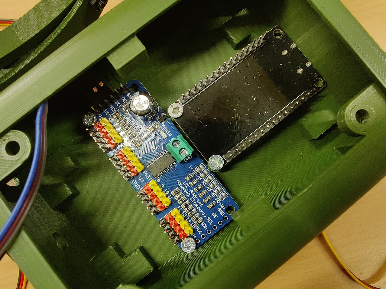
Electronics Layer 1 (negligible fit issues)
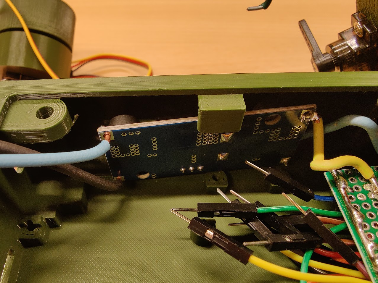
Electronics Layer 2 (cannot be inserted like this with Layer 1 installed)
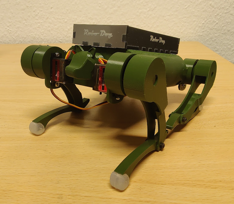
Partially assembled Functional Model
Due to the complications with the electronics, the functional model is yet to be completed.
Prusa MK4s and a trotec Speedy 100 laser cutter
PrusaSlicer 2.9.4, INKSCAPE and AUTODESK Fusion Personal (free)
PMMA, Prusament PLA Army Green, eSun PLA silk, eSun PLA+, Silikon SF45, SMOOTH-ON Ecoflex™ GEL
(for materials and software used in the design and build process of the electrical components, as well as a detailed look at the overall costs, please see Jan-Erik's page)