Nora Kurth
Feet and Shanks
Read about the process of designing new feet and their counterparts, as well as the journey of (silikone) pouring.
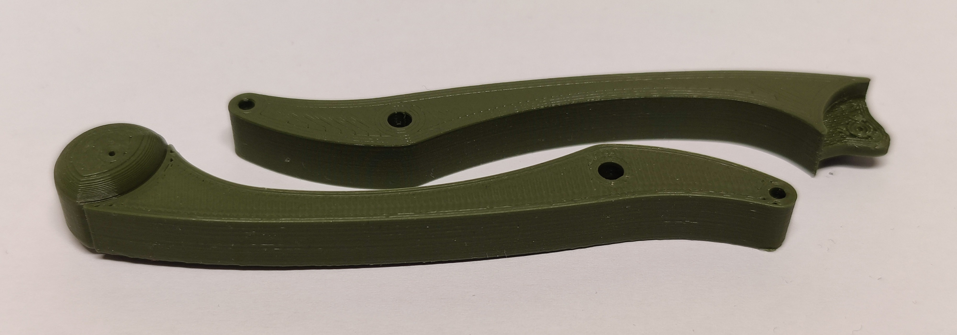
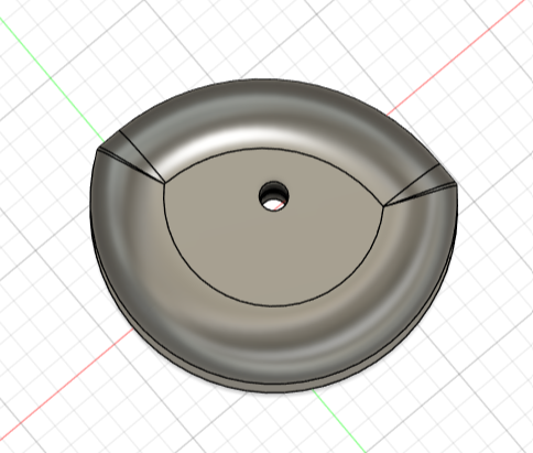
Shank with foot printed attached and with mount for poured foot
The Objective
The goal was to design feet that could be (cold) poured from rubber or silikone for better traction. So a new, but still practical design for both the foot and the lower end of the shank was needed.
Design Process of new Feet and Shanks
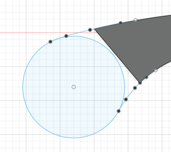
Not wanting to change the working geometry of the template, the first step was to trace the original foot.
Then this sketch was used as a guideline for the new sketch of the outline of the foot, as well as the end of the shank connecting to the foot.
Using extrusion and filleting operations, the new parts were modeled from this sketch.
To securely connect the foot to the shank, a hole for a pin (⌀ 0,9mm nail, cut to length) was designed.
Foot before
Foot after
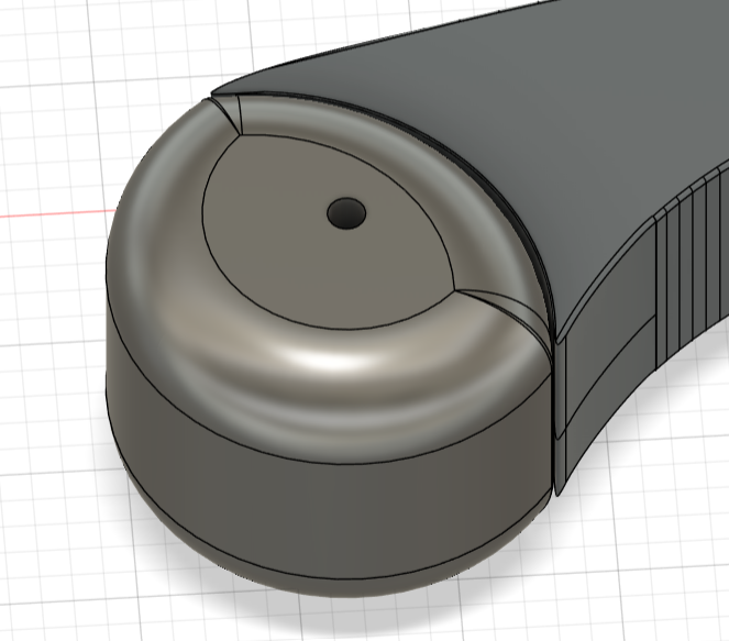
Shank after
Foot as seperate Part
Trace of Original
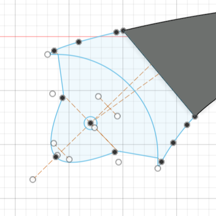
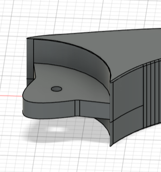
Sketch of New Shank
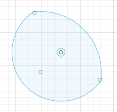
Sketch of New Foot

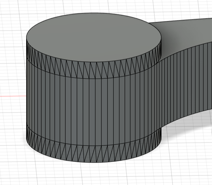
Complete Model of old Shank
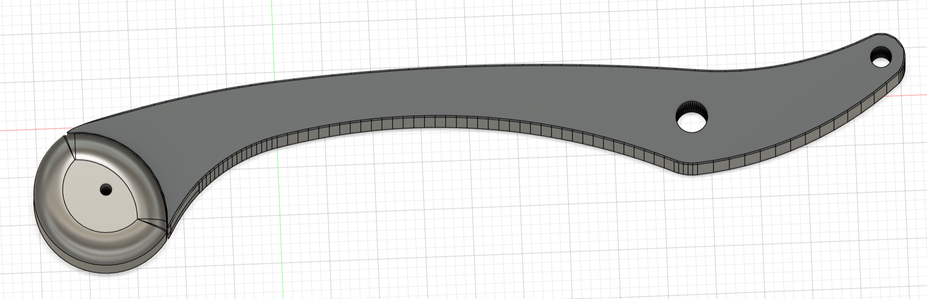
Complete Model of New Shank and Foot
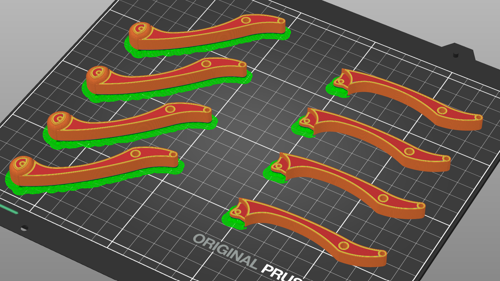
Shanks Sliced
Design Process of the Mold
Now the new challenge was to design a mold with which the feet could be cold poured with silicone. - The outcome of this process would be a three part (+needle/nail) mold. -
The rough form of the mold was created by using the model of the foot as a cutting tool in a cuboid bigger than the foot.
Next this cuboid was cut in half through the center of the recess the model of the foot created. The orientation of this cut was chosen in a manner, that the cut would also go down the middle of the narrow side of the shanks counterpart to the foot.
Some thinking was necessary to find a suitable location for the sprue. The first intention was to work with a single spout for the sprue, which only led to undercuts and it being impossible for the mold to fill completely. The solution were two spouts on either side of the inlay meeting at one funnel. Now many chamfer and filleting operations were necessary to model a sprue design capable of supporting the flow of the poured material.
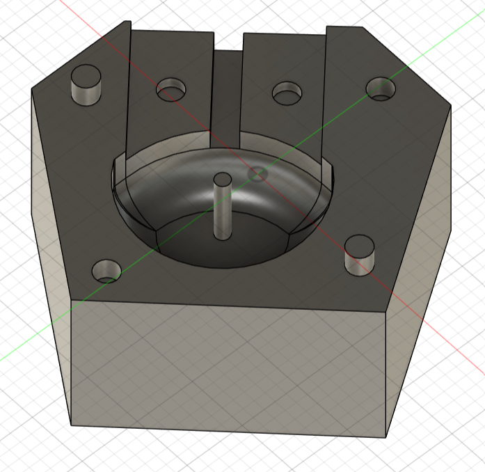
To stop the parts of the mold from moving against each other, a system of pins and holes was designed to secure them in place. Also some material of the cuboid was cut away. Not only to create a standing surface opposite of the spouts, but also to cut down on material wasted for the print of the mold.
In the first print the 'axles' proved to be to thin (1mm in CAD-model). So the design was changed to a nail or needle being inserted through all three parts of the mold.
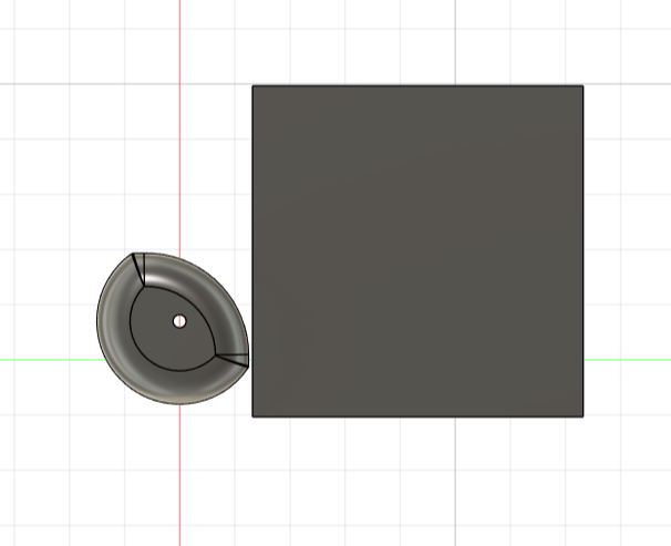
Foot and Cuboid
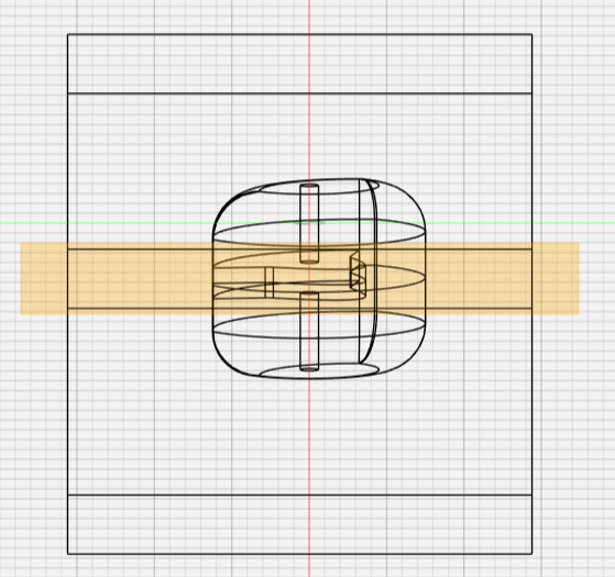
Splitting of the Cuboid
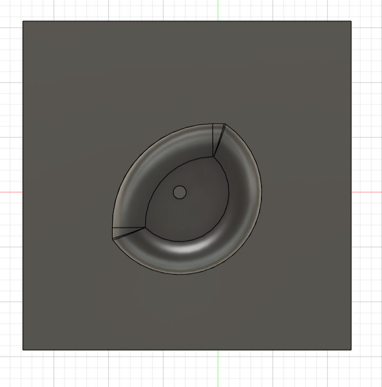
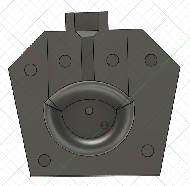
Recess of the Foot in the Cuboid
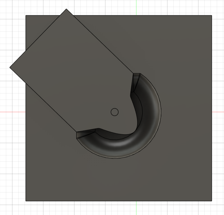
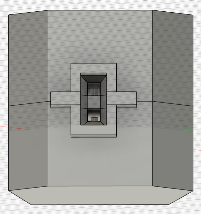
Cutout of the Shank as Inlay
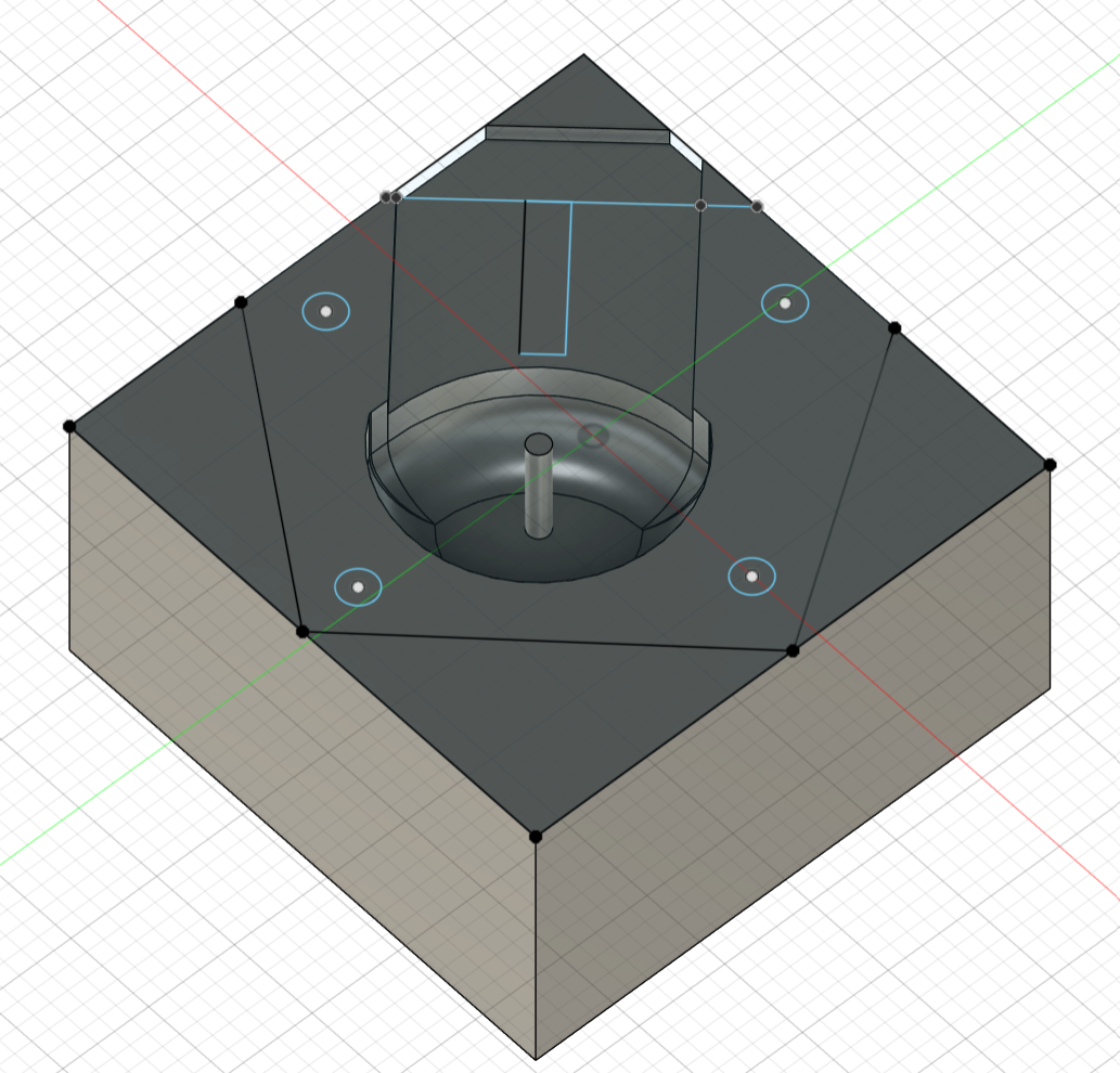
Rough Sketch of Spout and Location of Pins/Holes
Extrusion of the Sketch
Beginning of the Spout
Beginning of the Funnel
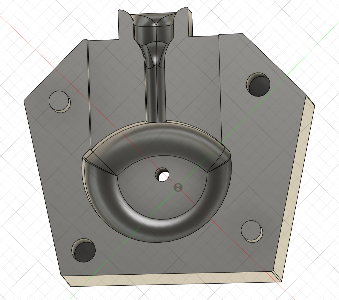
Finished Spout
Finnished Funnel
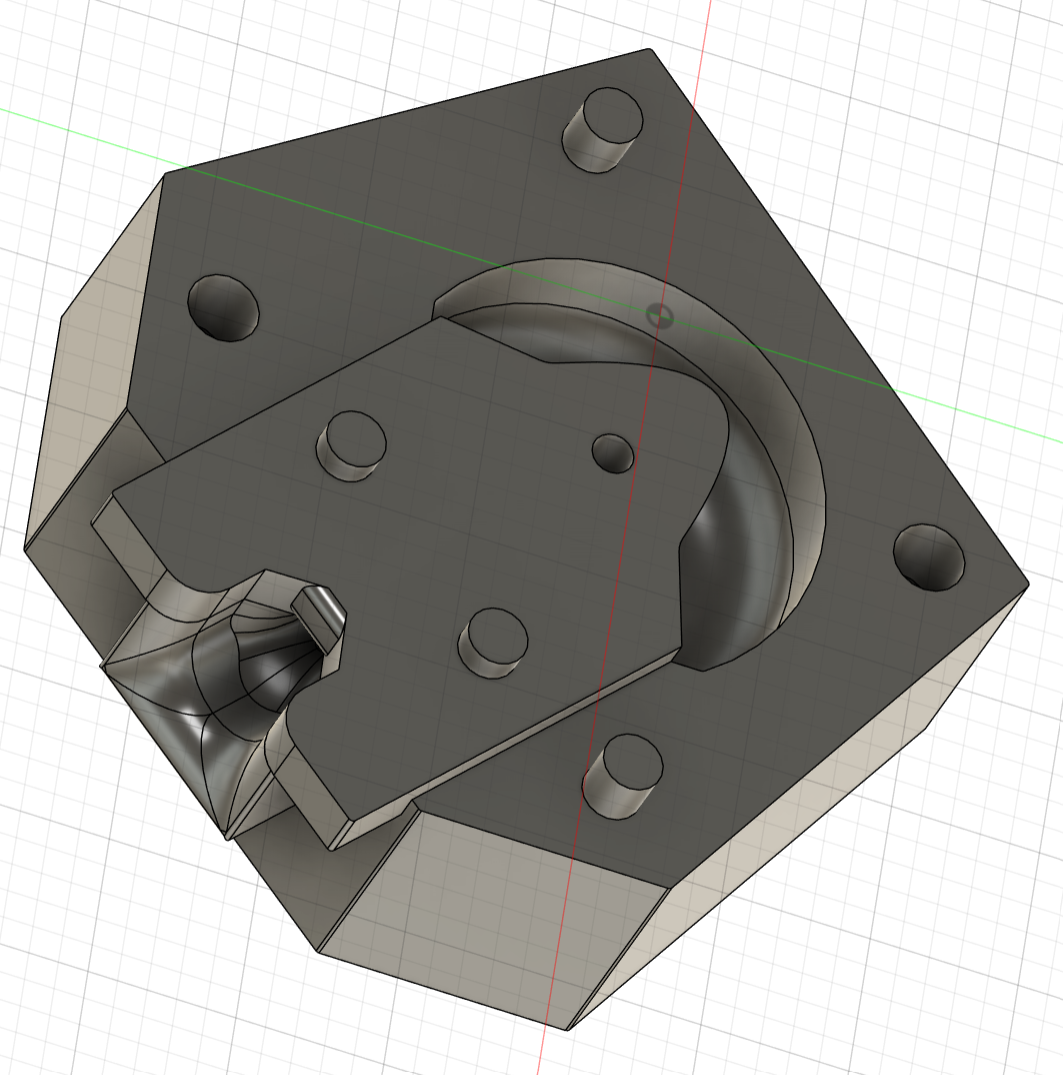
Finnished Mold with Inlay
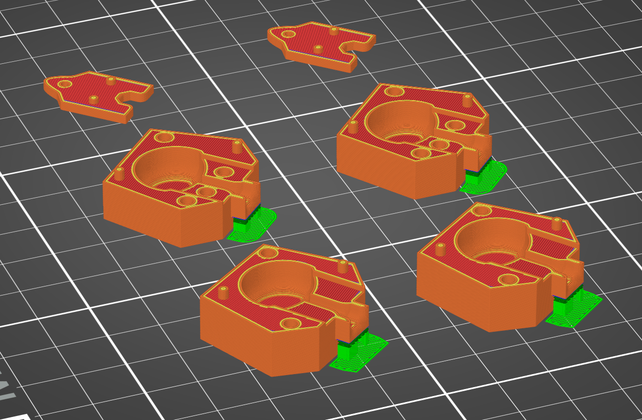
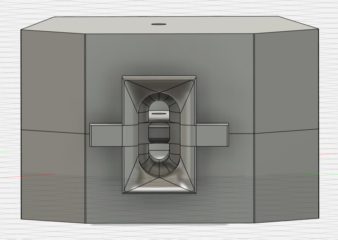
Mold Sliced
Excursion: Trouble with Print Accuracy and Surfaces
With the first prints of the mold, the issue of some structure not being true to measurement came up. The included offset was not enough and the variation of deviations was unpredictable.
These deviations seemed to be a lot less when a print of the mold was made with a different filament. This success could be repeated with another filament by the same company.
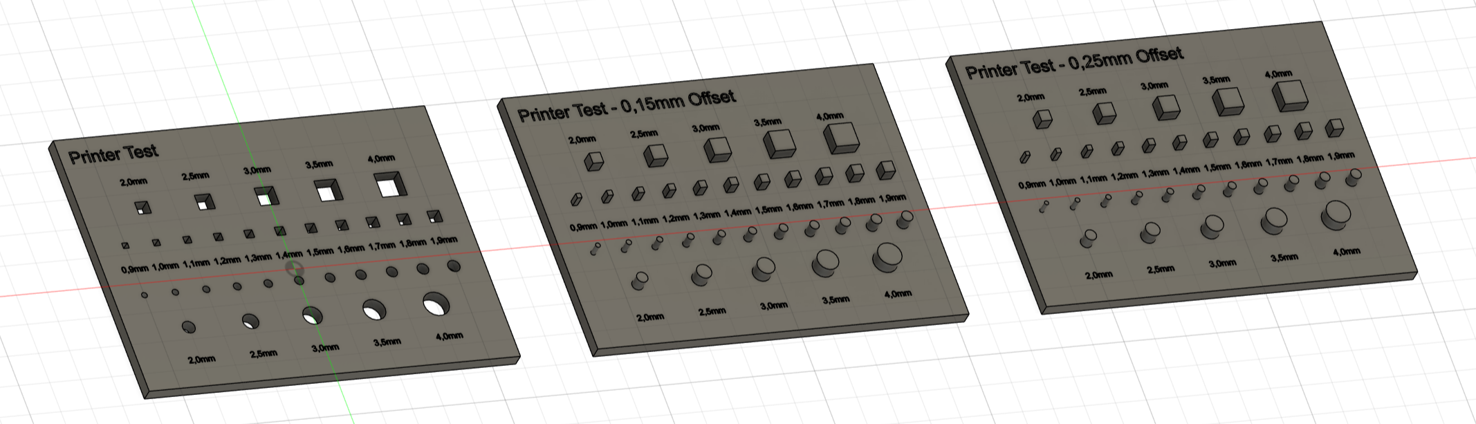
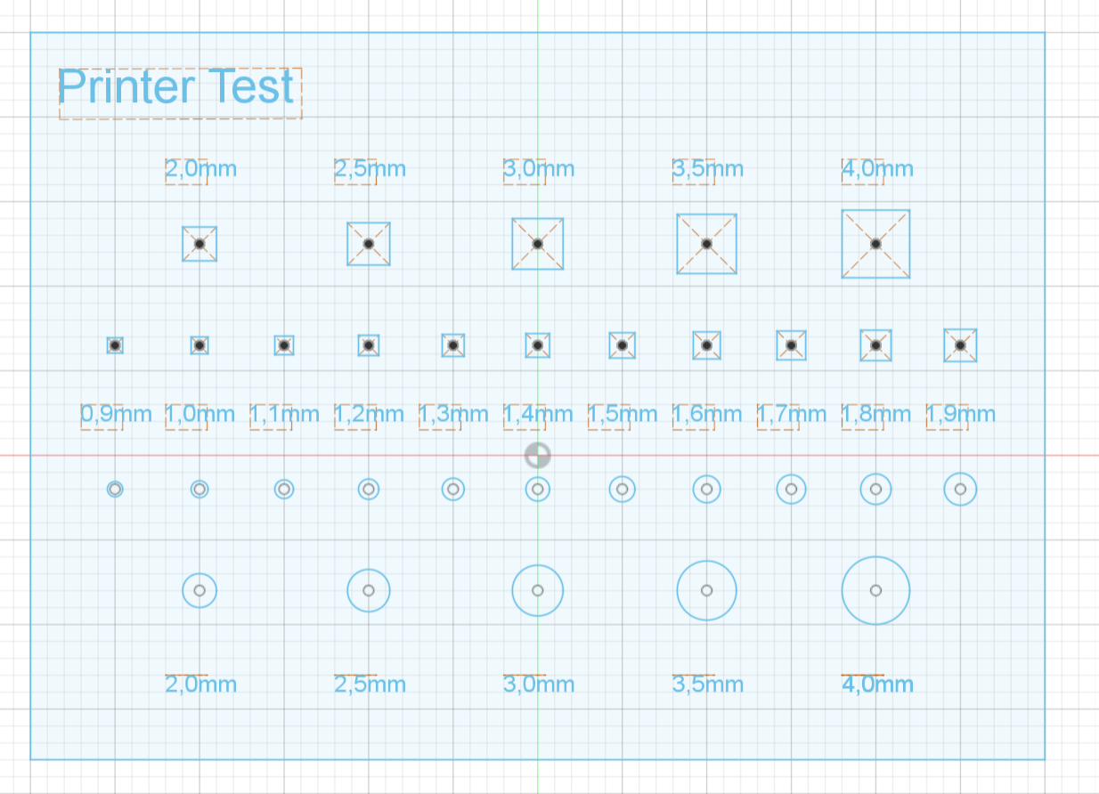
As the whole Robo Dog is currently very small, this discovery led to the design of a 'Filament Print Test'. The goal of this test is to find out, from which measurements upwards a filament prints (acceptably) true to measurement on a given printer.
The Test should show Holes from 0.9mm to 1.9mm in 0.1mm steps and from 2.0mm to 4.0mm in 0.5mm steps. The Pins should have an offset of 0.15mm and 0.25mm.
Filament Print Test - Try 1
This design looked nice and sleek in Fusion, a little bit problematic sliced and proved to be very nonfunctional when printed.
If one pin-hole combination does not fit, no other combination can be sufficiently tested. Also all inteded engravings were illegible.
Model of Try 1
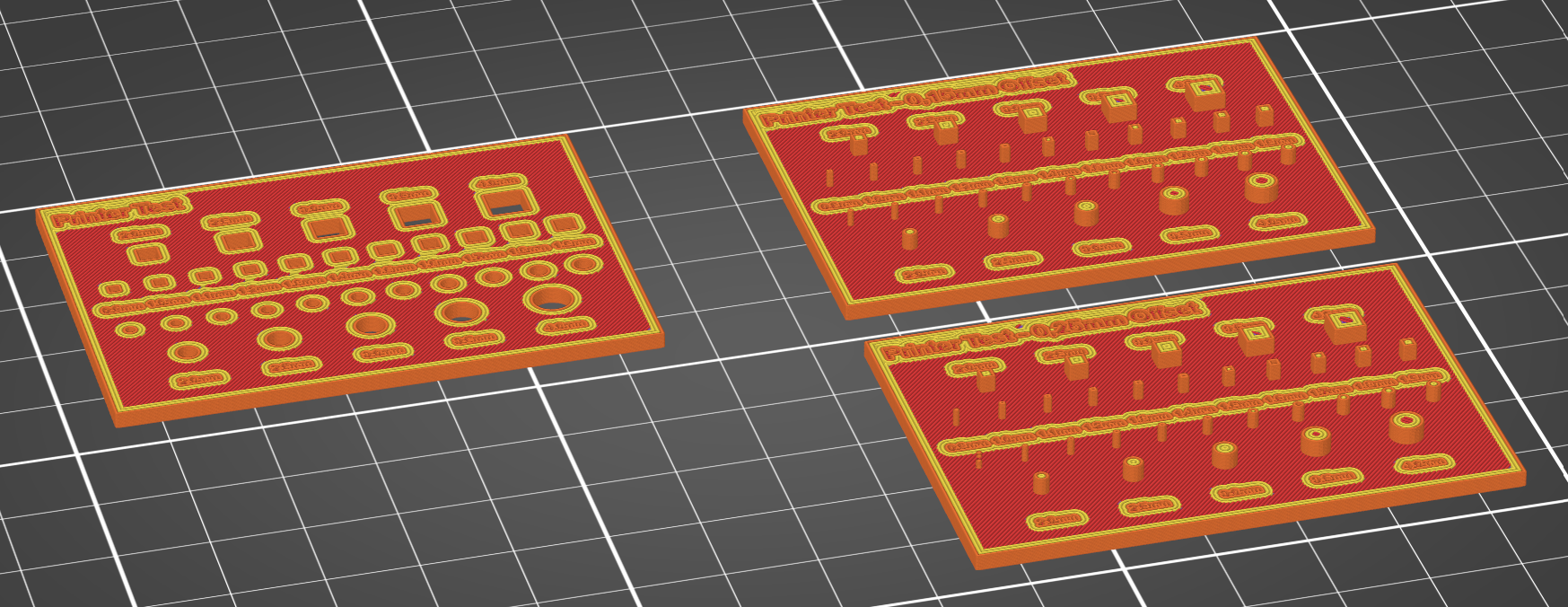
Try 1 scliced
Sketch of Hole Plate of Try 1
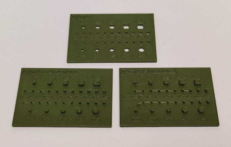
Try 1 printed with Prusament
Filament Print Test - Try 2
With the learnings of Try 1 and a reevaluation of the desired functionality, Try 2 was designed.
Redundant Pins were omitted and the spacing was designed so that each pin can fit into its corresponding hole(s) without needing other pins to fit. The only engraving used is a '1' for the 0.15mm and a '2' for the 0.25mm offset side of the bigger pins.
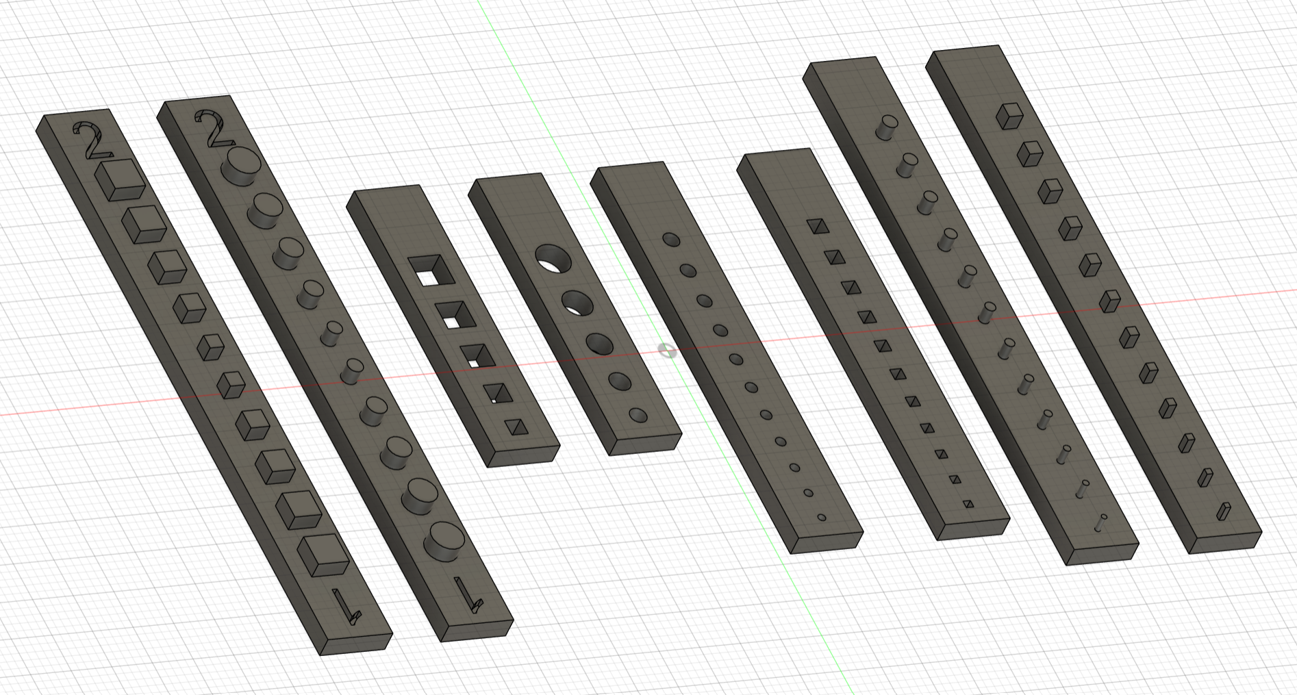
Model of Try 2
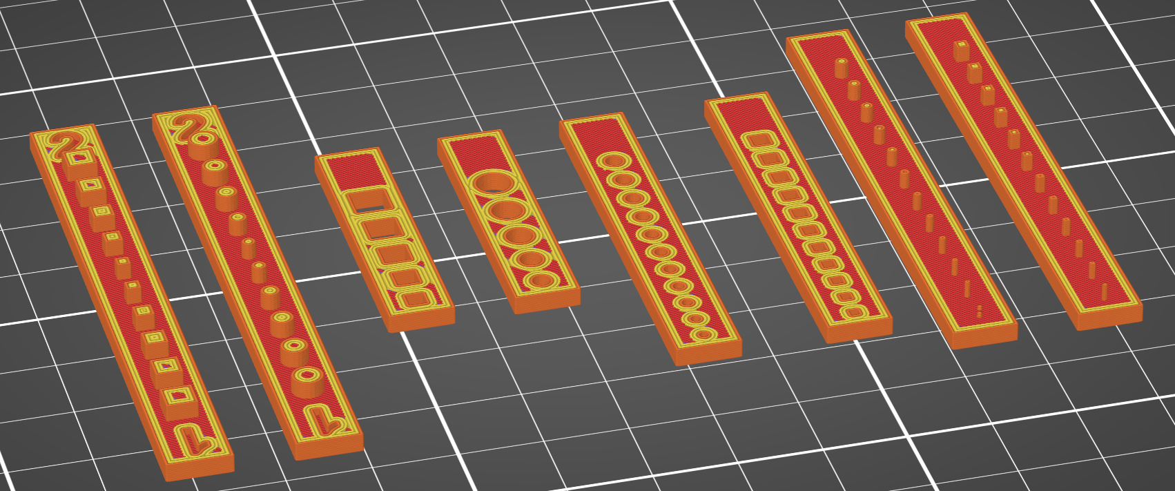
Try 2 scliced
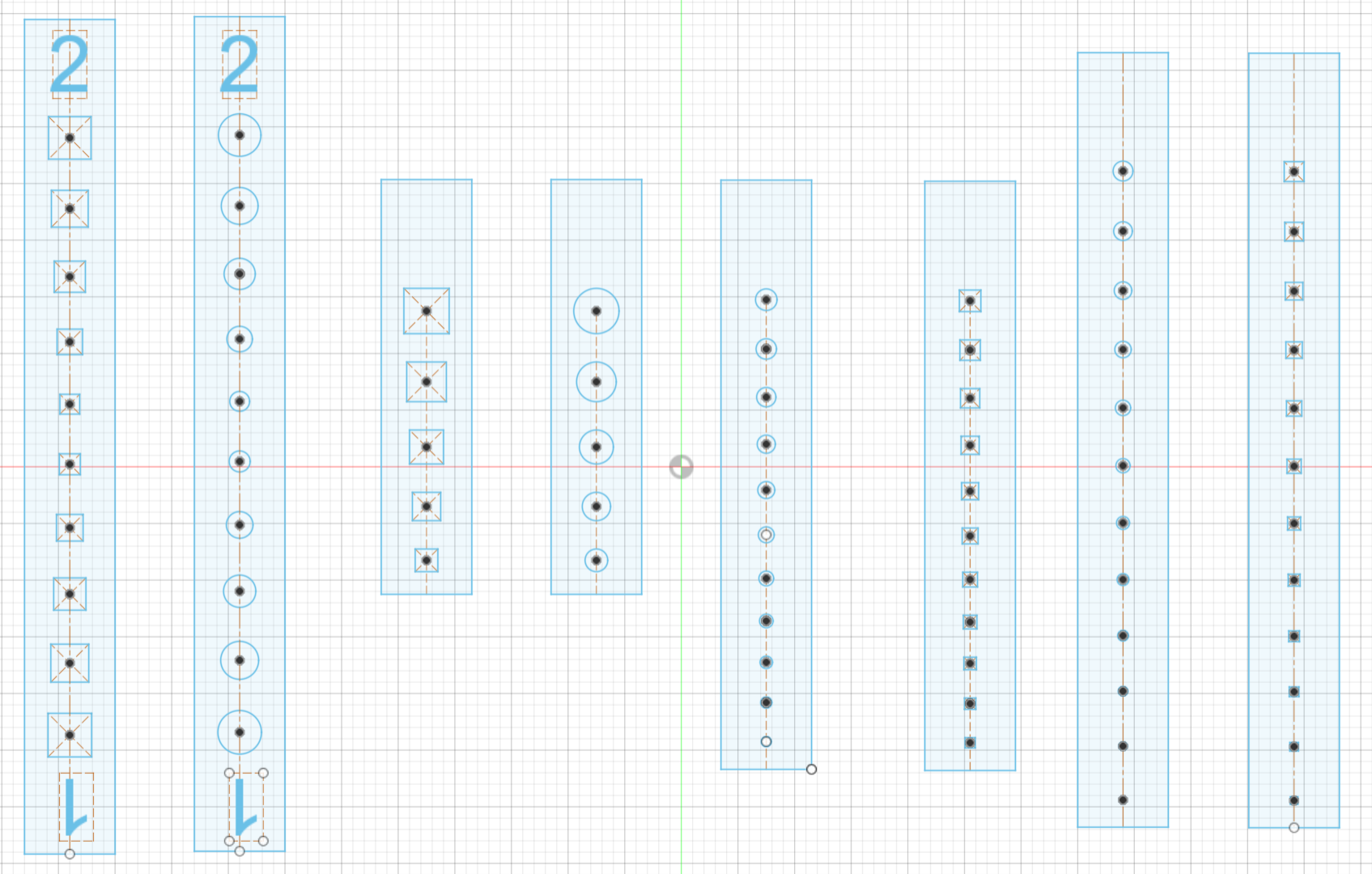
Sketch of Try 2
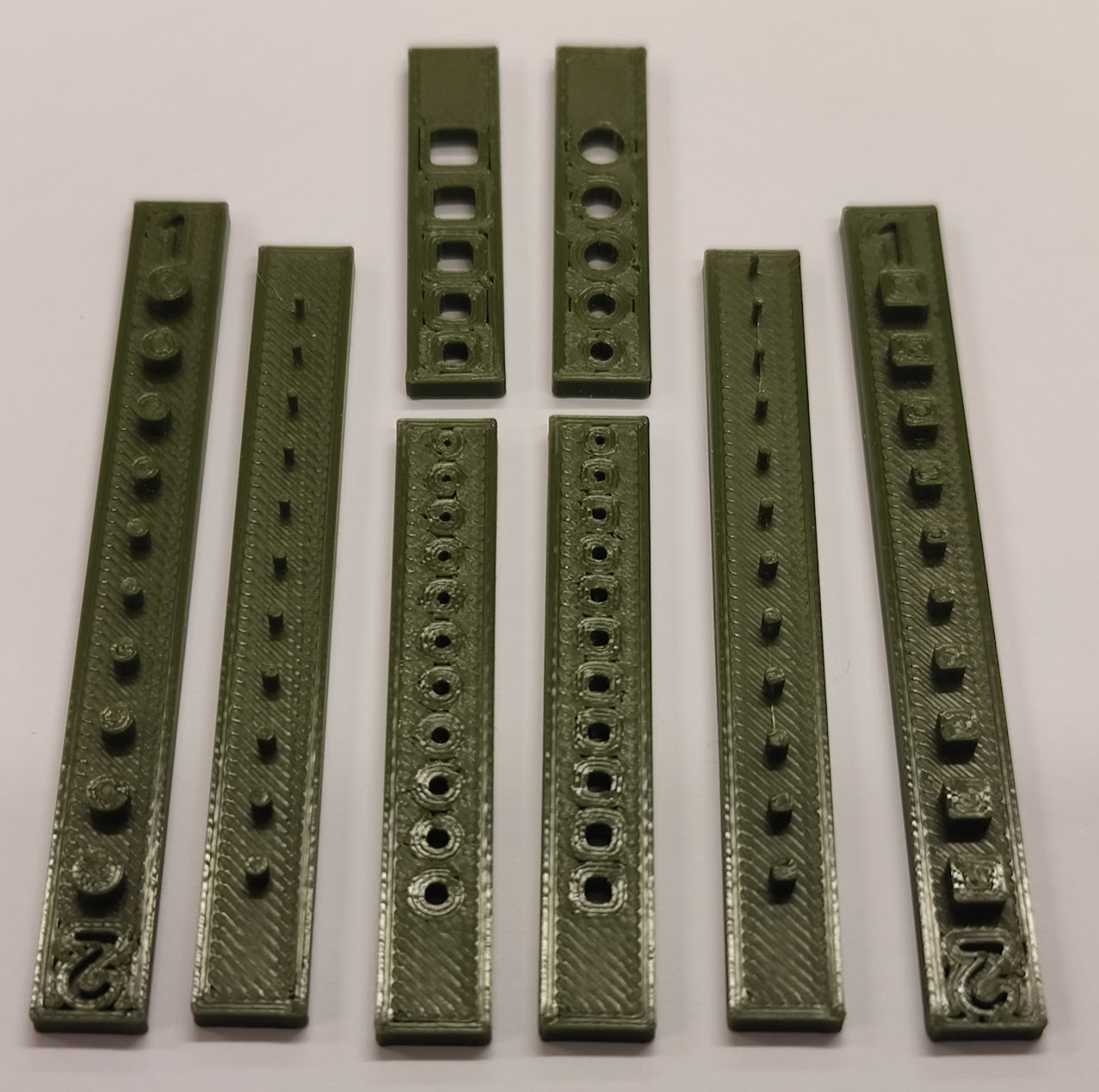
Try 2 Printed with Prusament
Silicone Pouring
Silicone was chosen as material, because it can be cold poured with PLA molds and without any special equipment.
Choosing the right silicone required consulting the Shore Hardness Scale, as there are many Silicones with just as many different hardness levels.
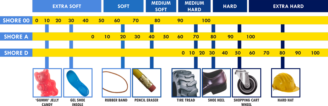
Source: smooth-on.com
Pouring - Try 1
The first mold printed already seemed to fit well enough to try and do a test pour.
Our lecturer had some SMOOTH-ON Ecoflex™ GEL available, which we used.
There were two serious issues with this silicone:
- It was too viscous for the size of the sprue, which led to it being impossible to fill the mold completely.
- At 000-35 (below the Shore Hardness Scale) it is far, far too soft for Robo Dogs feet.
Also the correct measuring and mixing of such small amounts of silicone as needed proved difficult.
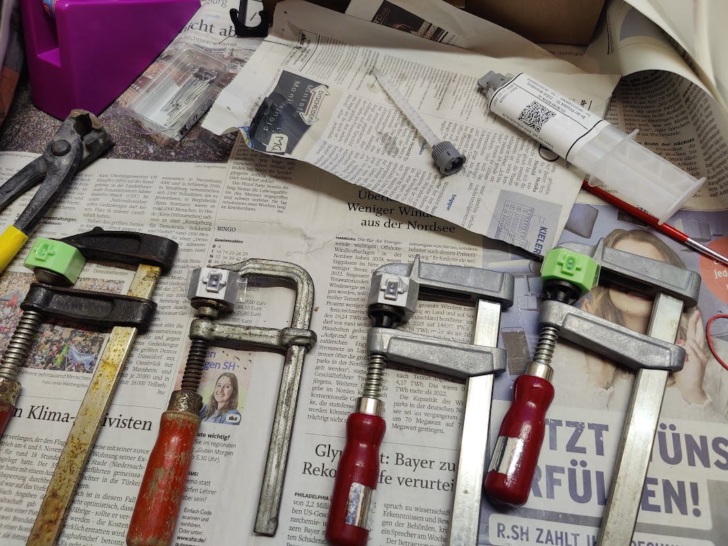
Preparation
Curing
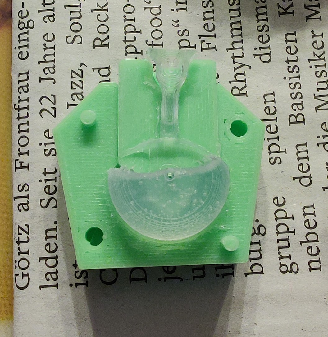
Result still in the Mold
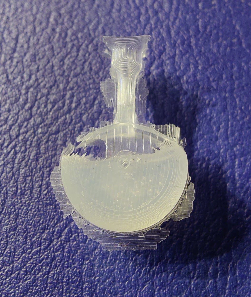
Result demolded
Result demolded with size reference in cm
Pouring - Try 2
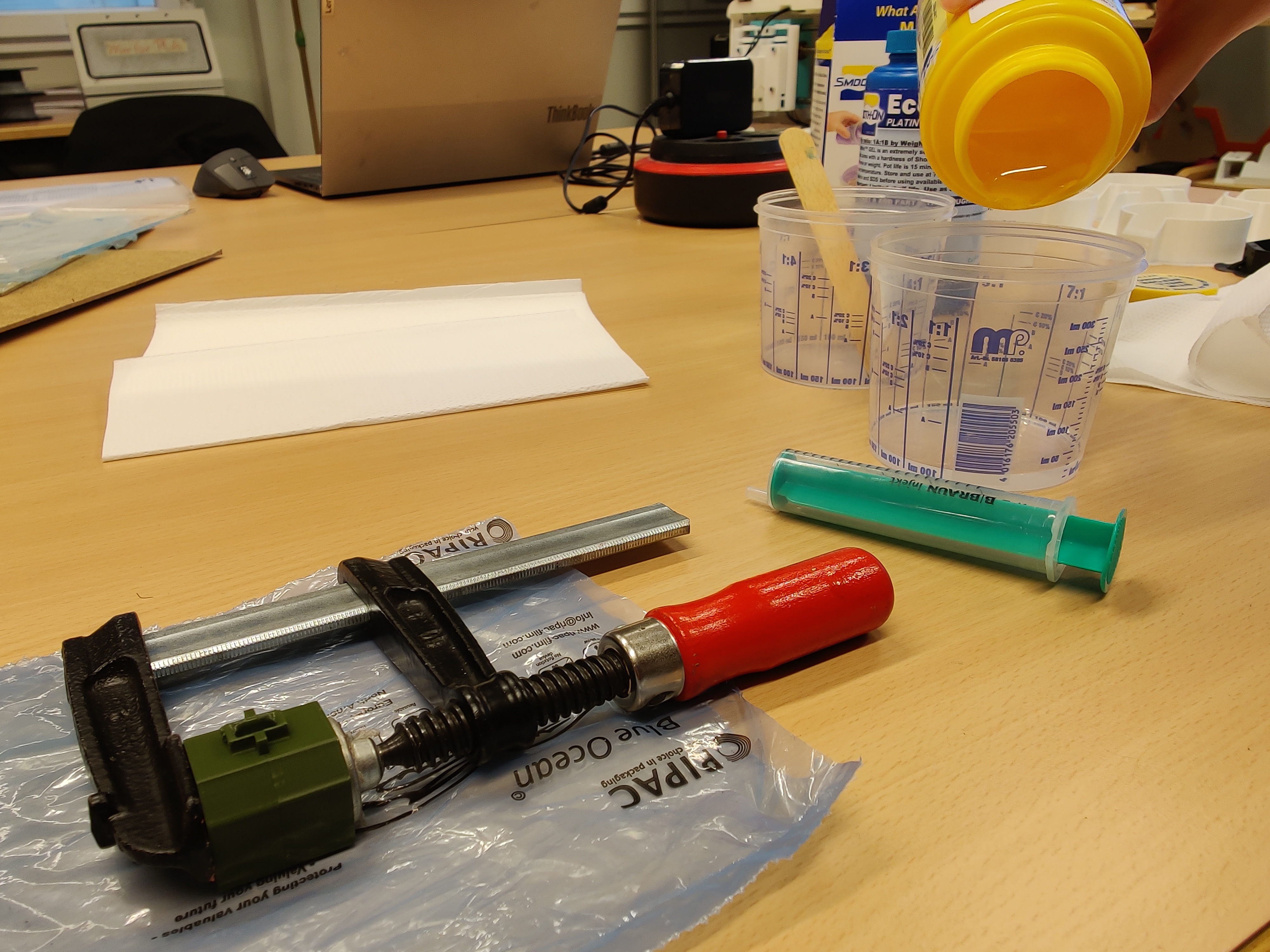
For the second - and hopefully last - try, a 26g dual cartridge of Silikon SF45 from silikonfabrik.de was ordered.
This silicone has a Shore Hardness of A-45, considerably more suitable for robot feet, than the silicone used in Try 1.
The benefit of the dual cartridge is, that it is supplied with a replaceable mixing nozzle. This allows precise dosing and enables bubble-free, accurate mixing even in very small quantities.
Even if this try should fail again, there is enough material for a third or even fourth try with all four feet: This silicone has a mass-density of 1.12g/ccm and one foot has a volume of about 1.5ccm, leading to one foot requiring 1,68g of material. Minus material lost in the mixing nozzle, pouring allowance and spills - there are still at least 10 feet in the dual cartridge.
This try had the desired hardness, but the molds again did not fill completely due to the still relativly high viscosity of the used silicone.
Positive takeaways from this try were: the talcum very thinnly brushed onto the molds worked great as release agent and the nails connecting all three parts of the mold worked as intended, too.
Pouring of Try 2
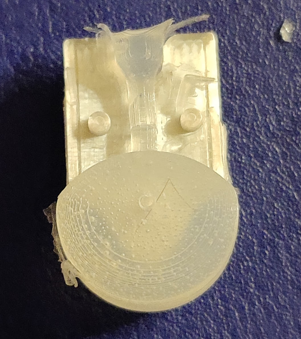
Try 2 still in the Mold
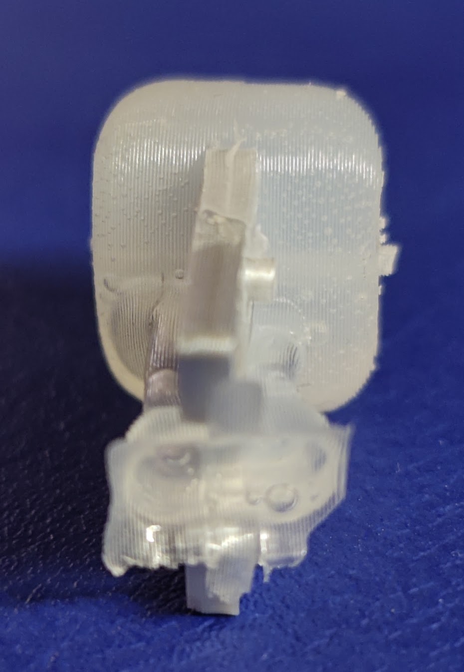
Try 2 demolded - Sideview
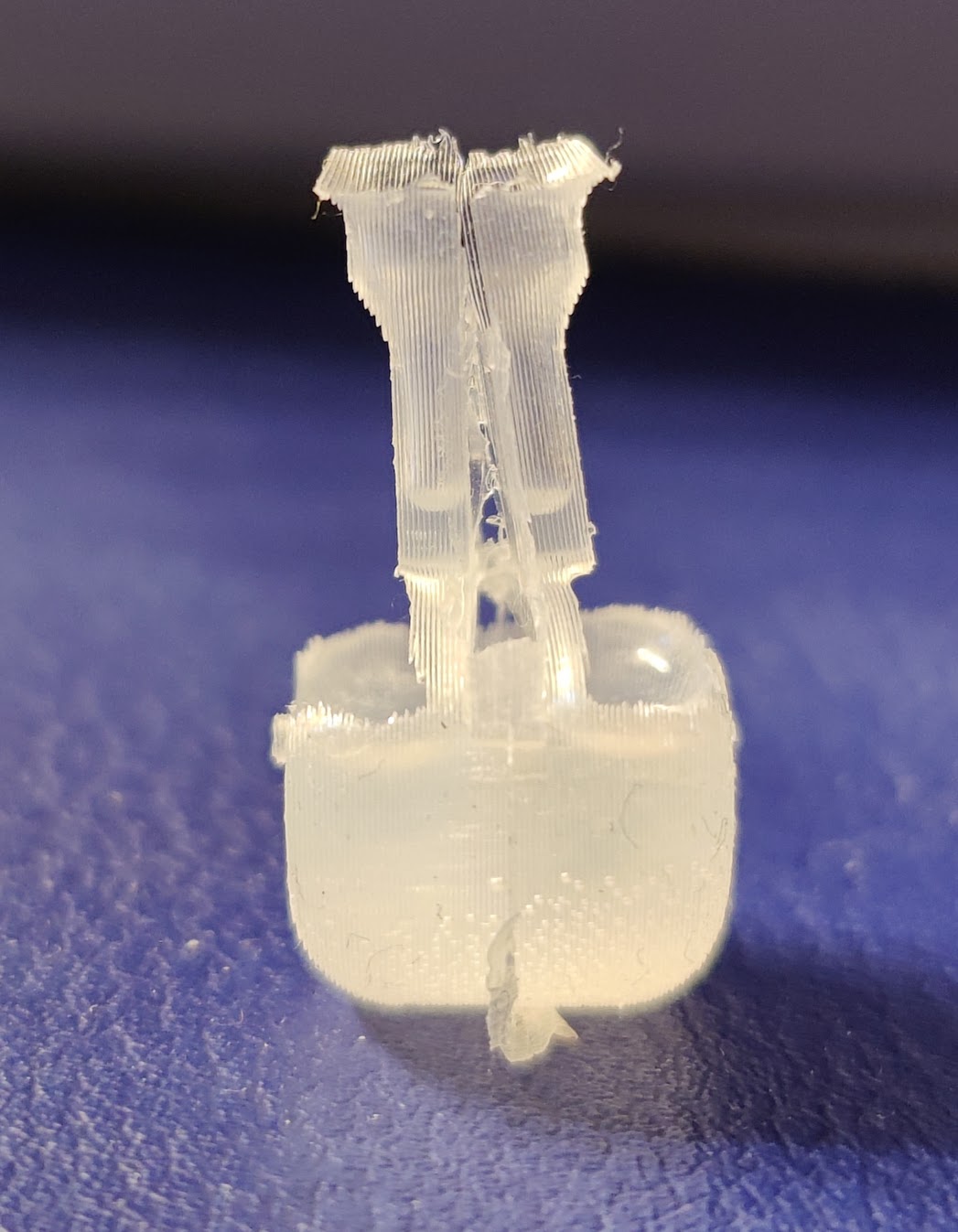
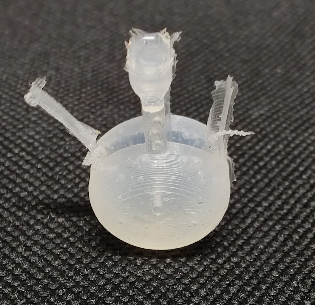
Try 2 demolded - Frontview
Pouring - Try 3
For the third try, the molds and the remaining silicone from Try 2 were (re-)used. This time the molds were filled as much as possible before beeing assemled.
While this method worked a lot better than the previous one and produced usable feet, further improvement of the mold and the process would be benificial. Eliminating bigger air pockets still present in this try would be the goal of this improvement.
A conceivable measure would be redesigning the funnel and spout of the sprue to allow the nozzle of the double cartridge to reach all the way down to the cavity of the assemled mold. This should facilitate the complete filling of the mold and prevent bigger air pockets. Another, but harder to implement measure, would be to insert the filled molds into a small vacuum chamber to further reduce trapped air.
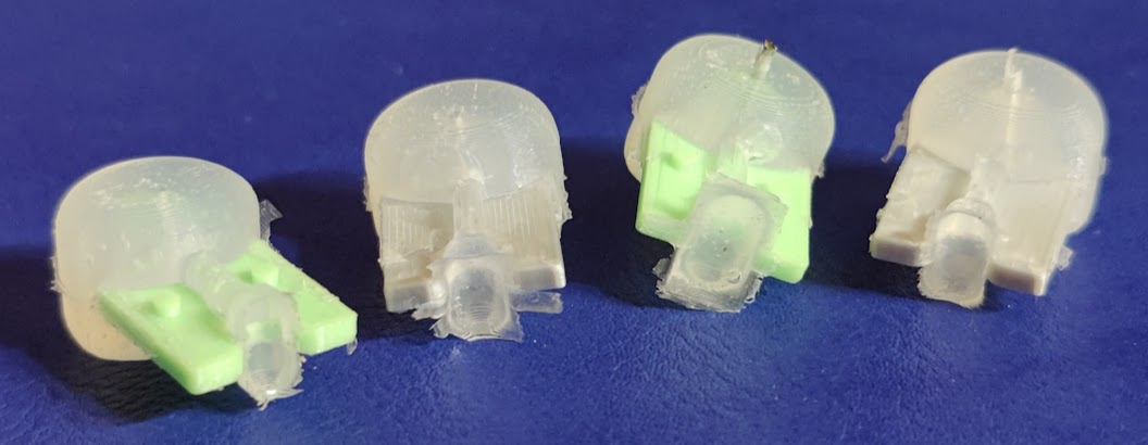
Partially demolded Try 3
Try 3 with Inlay still between the Sprue
Top of the Sprue
Try 3 fully demolded
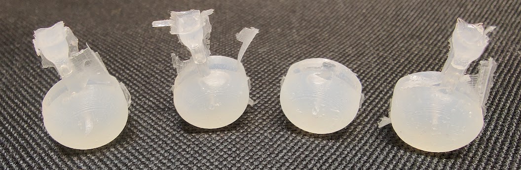
Fully demolded with Sprue still attached
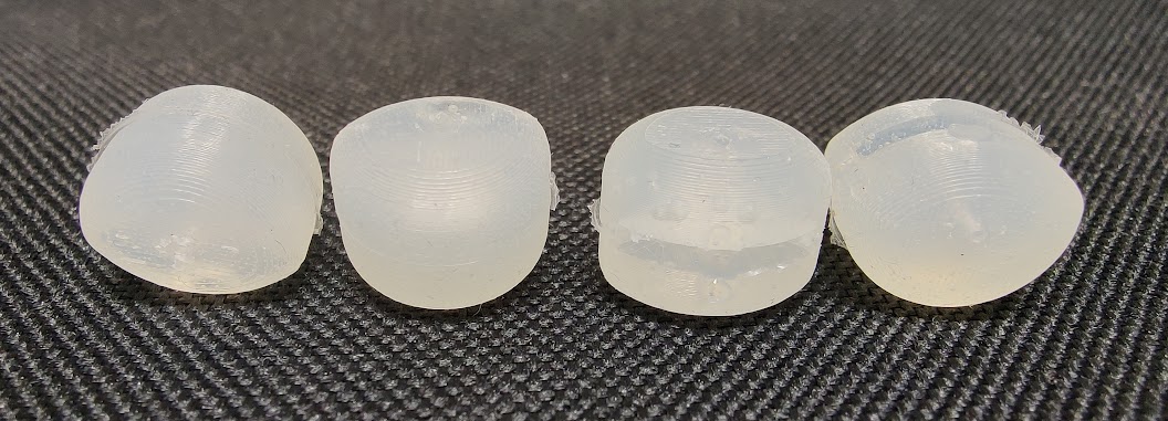
Demolded and cleaned Try 3
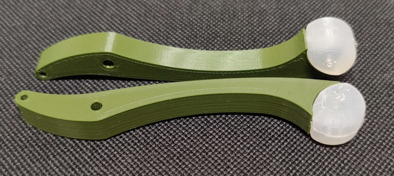
Finished Shanks and Feet
Back to the main project page.