Nora Kurth
Main Body and Lid
The Quest for more space. And making the most of the space available.
Important Sketches of the Main Body
The Objective
To fit all the electrical components after some of them were changed and new ones added, new internal structures of the body were needed.
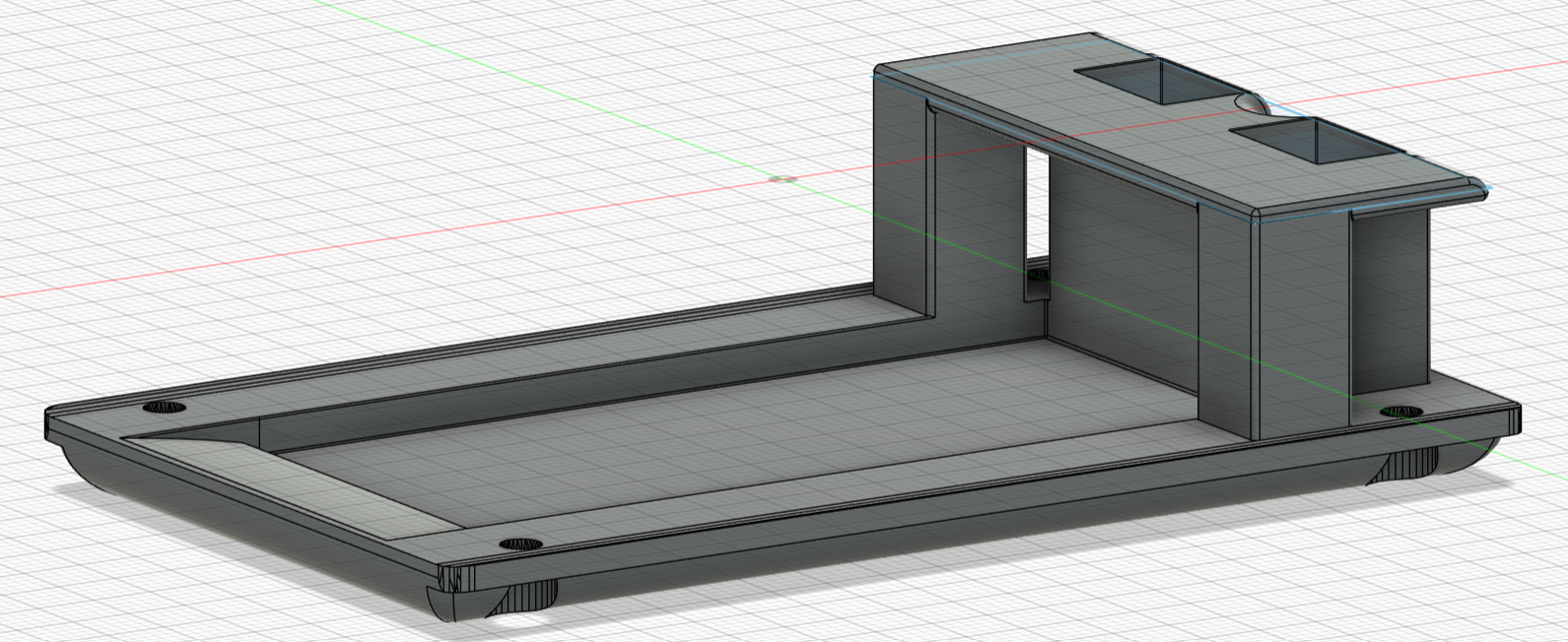
For the future implementation of the follow feature more space than available in the body was needed. This and the desire for more dog-like optics lead to the idea of adding a head and tail. For these components a means to attach them to the body had to be designed.
Further there had to be a structure to keep the tray form sliding off of Robo Dogs back.
Changes to the Main Body
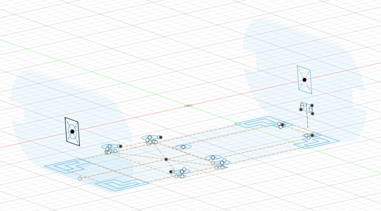
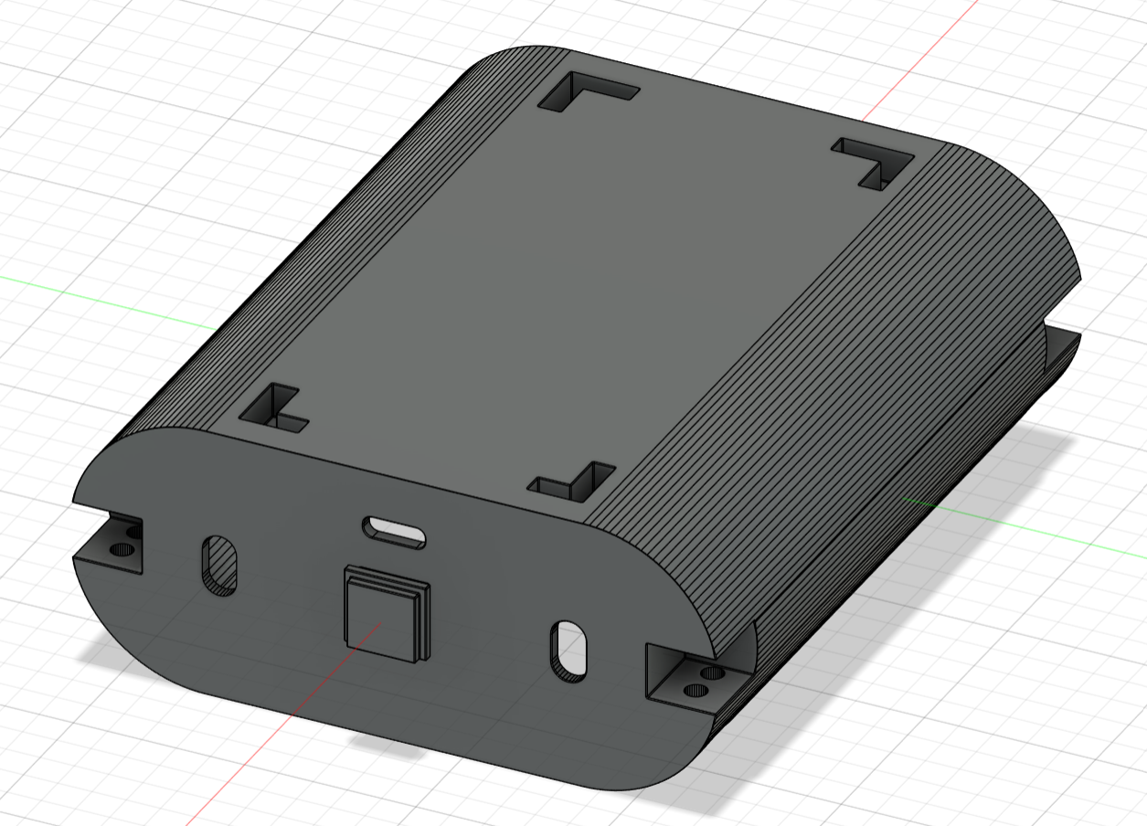
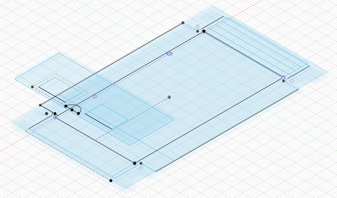
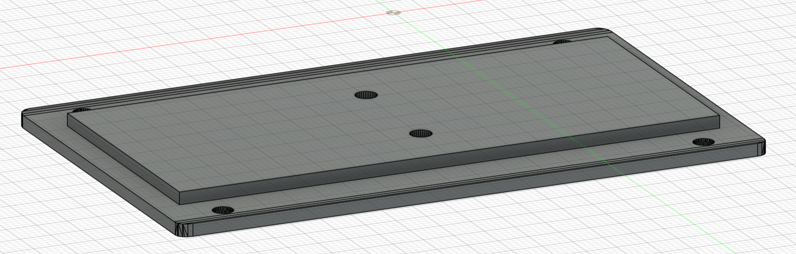
First were the receivers for the tray. In each corner of the flat top of the body slots were designed for counterparts on the bottom of the tray to fit into. These were sketched and then modeled into the inside of the body via extrusion operations.
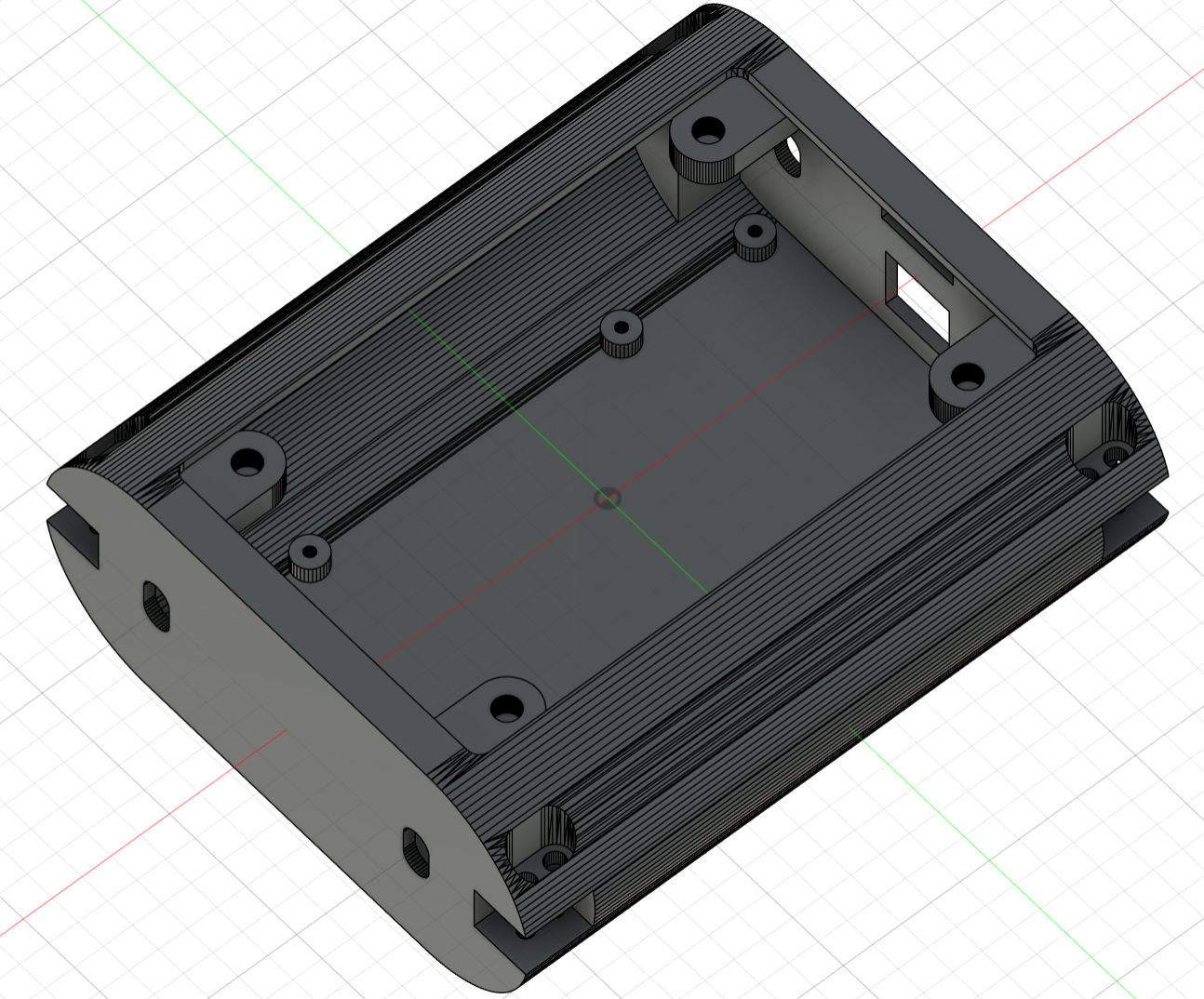
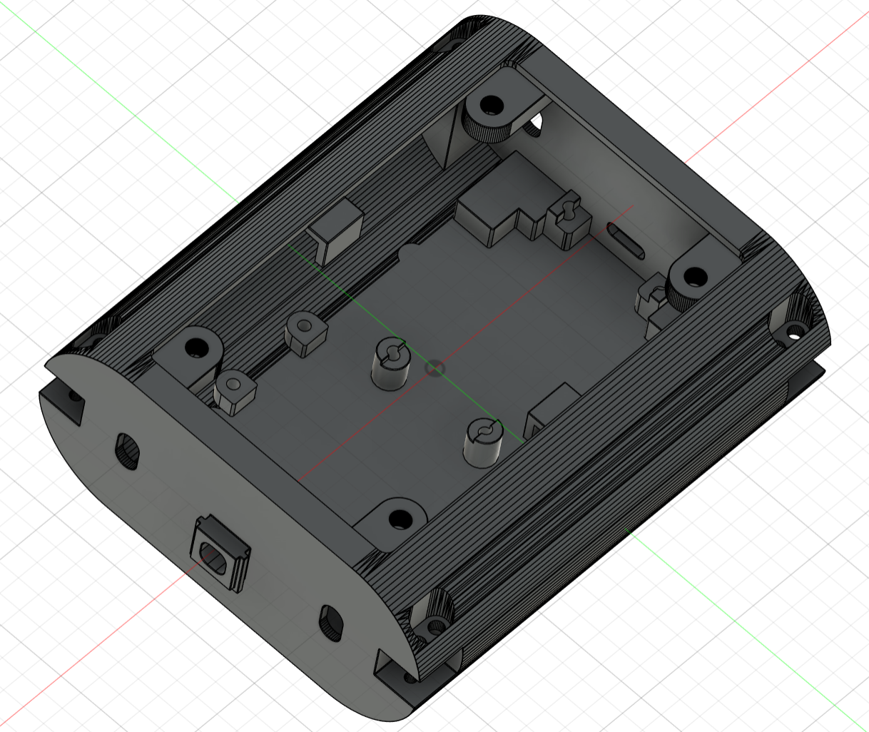
Next the task of fitting the electrical components was tackled. Here close communication with Jan-Erik about the internal layout and precise measurment - the dimensions given online could NOT be trusted - were paramount. After the supports of the template were removed and not needed holes closed, the positions of the new supports were added to the first sketch (main sketch) and the position of new openings in the front (for cables to the head) and in the back (for the USB-Port for programming) were also sketched in two new sketches.
After the sketches were done the stuctures were formed via further extrusion operations. During this process some additional sketches were needed at the receivers for the head and tail to cut the notches. One additional sketch could have been avoided, if the inside instead of the outside of the top had been chosen as plane for the main sketch.
To hold some components without designated mounts in place in the sides of the body, small protrusions were added at the edge of the opening for the lid. These would later prove fatal when trying to assemble the functional model.
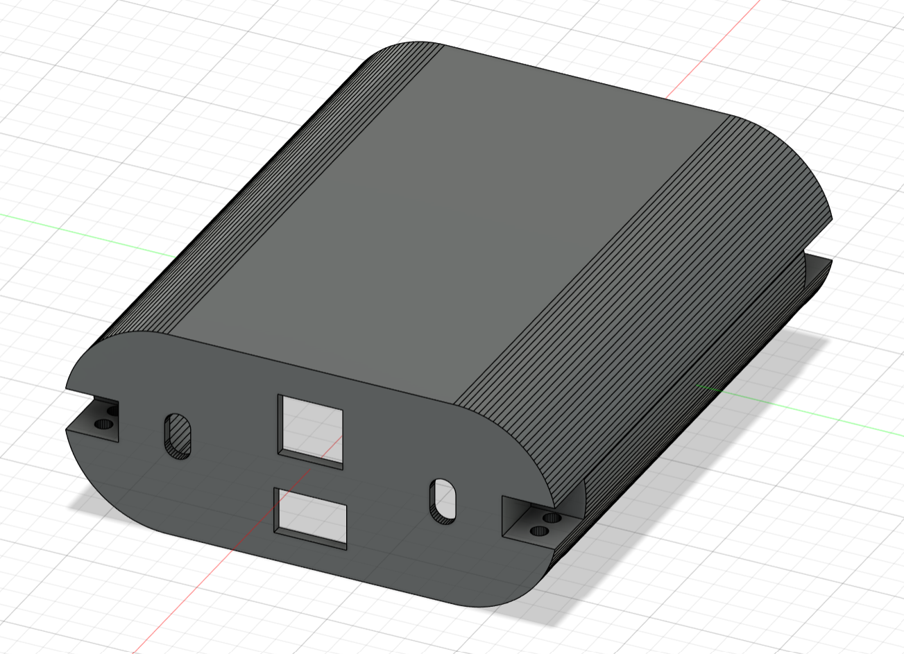
As a last step most sharp edges and corners were filleted.
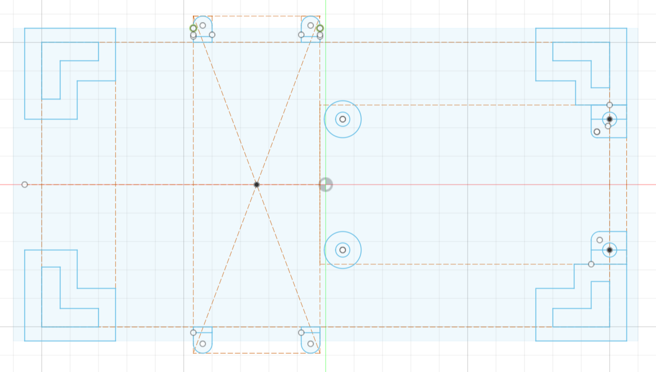
Main Sketch
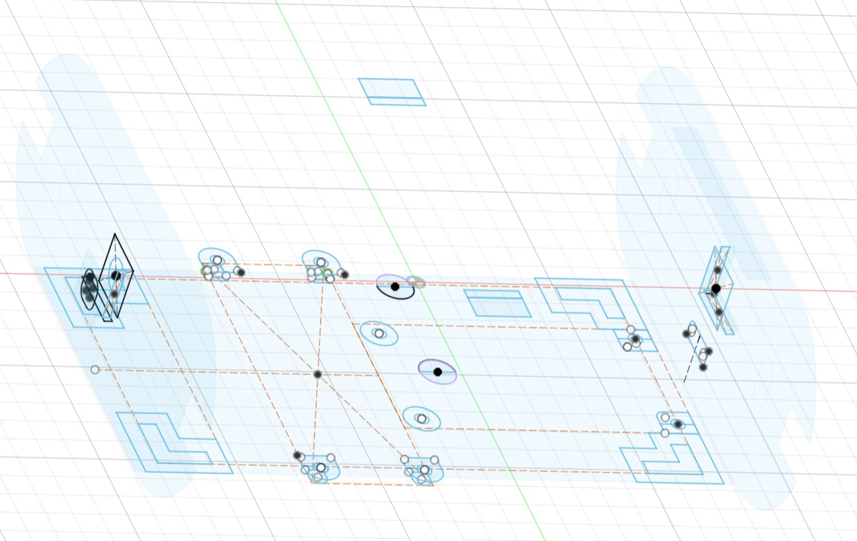
All Sketches used
Top of the Template Body
Top of the Finished Body
Bottom of the Template Body
Bottom of the Finished Body
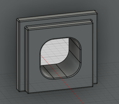
Connector for the Head
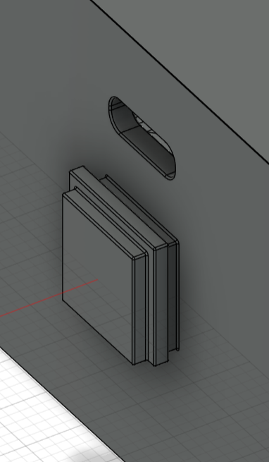
Connector for the Tail
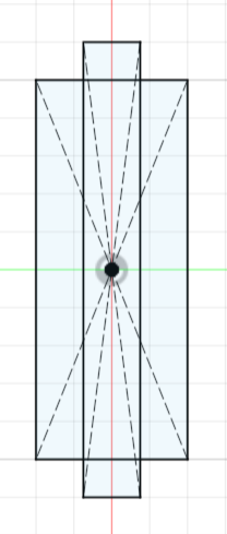
Additional Sketch for the Connector
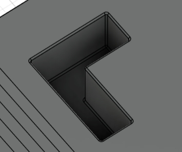
Receptor for the Tray
Changes to the Lid of the Body
After mentally fitting all the components into the main body, it became clear that the intended battery would need more space than available with the original lid.
To make more space, Robo Dog was given a 'belly' via extrusion operations with the help of a sketch on the flat part of the lid.
Additionally a 'shelf', with two extra recesses for small parts or cable management, was designed for a self-soldered board of relatively variable dimensions. To allow for insertion of the battery to remain possible beneath this structure, the opposite side of the indentation for the battery was flattened using filleting and chamfer operations.
During the entirety of this design process, the dimensions of the counterparts to the screwholes had to be kept in mind. To aid this, the main sketch excludes the area underneath them.
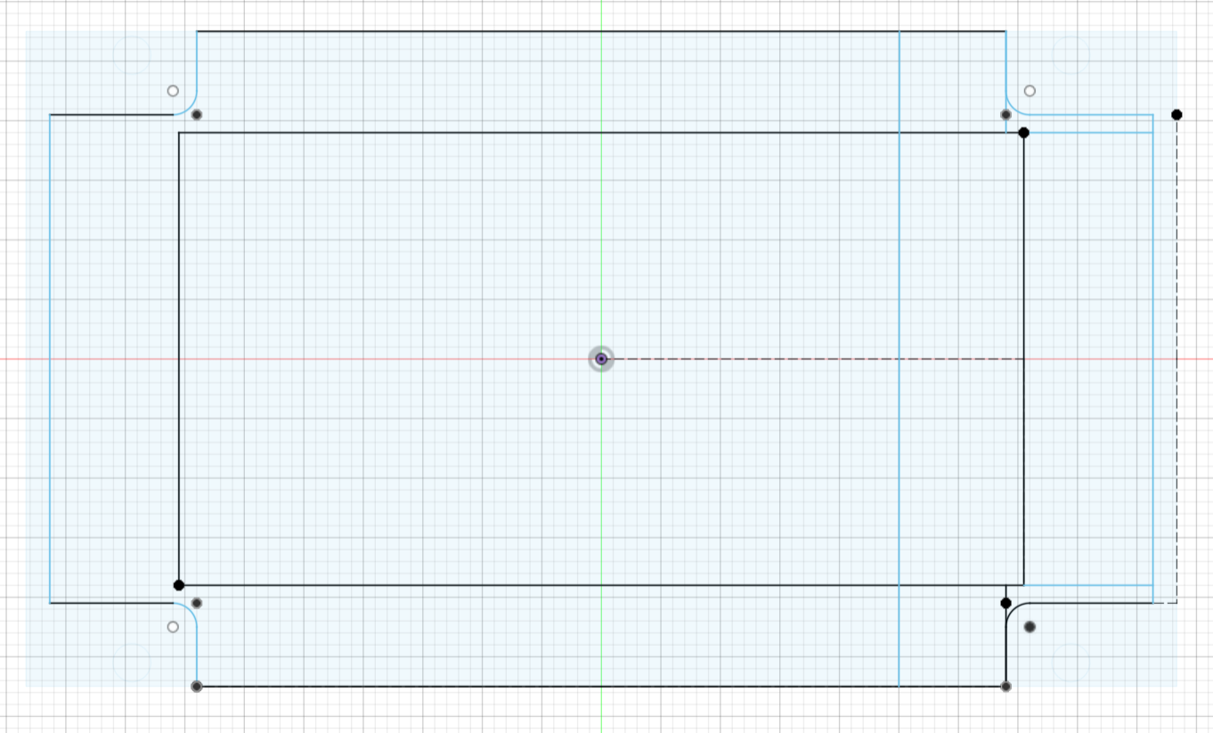
Main Sketch
All Sketches used
Template Lid
Finished Lid
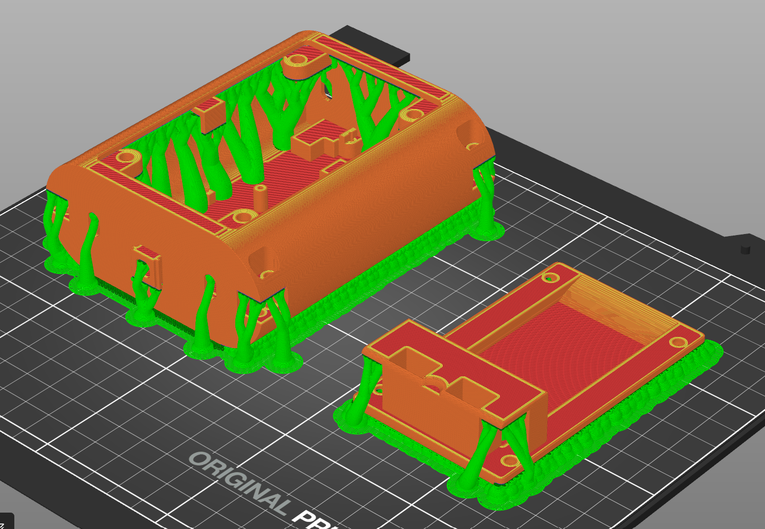
Body and Lid scliced
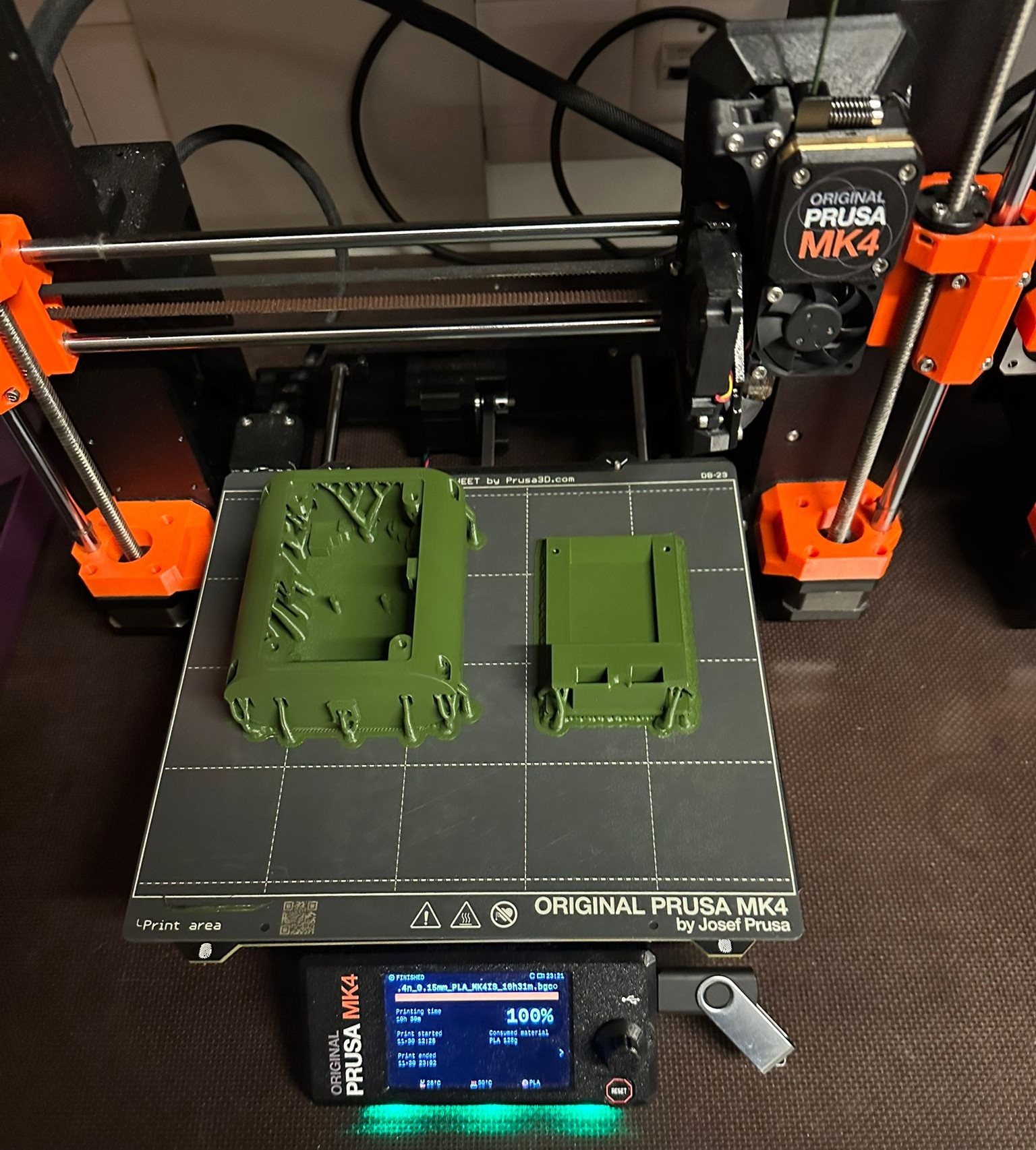
First Print of the Body and Lid
Back to the main project page.